|
 |
|
{Page 144}
School of Aerospace, Mechanical and Nuclear Engineering, University of Oklahoma, Norman, Oklahoma
The paper describes three different rectangular plate bending elements based on Reissner's type stationary variational principles. They differ in the number of dependent variables approximated independently and also in the number of nodes per element. The first element types treats the transverse deflection and the three moments as unknowns at each of the corner nodes; the second element type treats the transverse deflection and two normal moments as unknowns at the corner nodes; the third one treats the transverse deflection as unknown at the corner node, and the moments mx and my at the midnodes of opposite sides of the rectangle. These three types of elements are used to solve square plate problems with various boundary conditions and loadings.
| Introduction | Formulation | Numerical Results | Summary and Conclusions | References | Table of Contents | Home |
Owing to the severe continuity requirements placed on the trial functions employed in the conventional (conforming) finite element models of plate bending (derived with the total potential energy principle), the resulting element matrices are algebraically complex and consequently their solutions require large amounts of computing time. Further, the moments (or stresses) computed using the conventional plate bending elements are not accurate. To avoid these problems Herrmann (1) suggested a new triangular plate bending element which treats the transverse deflection and normal and tangential moments as unknown dependent variables. This element was derived using Reissner's variational principle for a thin plate bending element. Reissner's variational principle yields, as Euler equations, the moment-equilibrium equations and the kinematic relations connecting the transverse displacement (and its derivatives) to the moments. These equations are lower order (2nd order) compared to the fourth-order (biharmonic) equation governing the transverse displacement of the plate. This attractive feature relaxes the continuity requirements on the trial functions. Several mixed finite element models have been derived based on variants of Reissner's functional and/or using various order polynomial approximations (see, for example, (2-6) ). The present paper describes construction and applications of three mixed rectangular finite elements.
| Introduction | Formulation | Numerical Results | Summary and Conclusions | References | Table of Contents | Home |
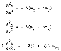
Let the middle plane of the plate to be analyzed be denoted WÌR2 with piecewise smooth boundary ¶W. This region is decomposed into finite elements {We}eN= 1. Let w denote the transverse deflection, mx, my, and mxy the moments, and P the lateral load in the plate. The kinematic relations are given by
 |
Eq. 1 |
where S = 12/Et3, E being the Young's modulus, t the thickness, and µ is the Poisson's ratio of the plate. The equilibrium equation is given by
 |
Eq. 2 |
These equations must be adjoined by appropriate conditions on the boundary of the plate. We introduce the notation
 |
Eq. 3 |
where nx = cos(n,x) and ny = cos(n,y) are the direction cosines of the outward normal n = (nx,ny ) on ¶W . We specify the following set of boundary conditions.
{Page 145}
(a) essential boundary conditions:
| Eq. 4 |
(b) natural boundary conditions:
| Eq. 5 |
Here variables with "![]() " denote specified values, and ¶Ww and ¶Wm are disjoint sets whose union is ¶W.
" denote specified values, and ¶Ww and ¶Wm are disjoint sets whose union is ¶W.
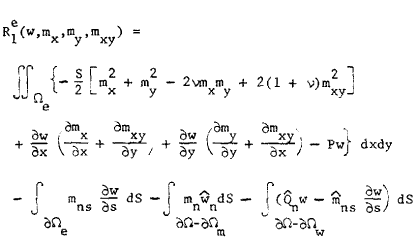
A variational formulation of Equations 1-5 has been derived (7) and is given by
 |
Here R1eis the restriction of the functional R1 to element e, and
 |
Eq. 6 |
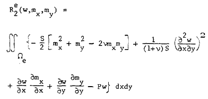
wherein for the sake of brevity the element label 'e' is omitted. This functional can be used to construct independent approximations of w,mx,my and mxy . If we assume that the third equation in Equation 1 is identically satisfied (i.e., eliminating mxy ), we obtain from R1e,
 |
Eq. 7 |
wherein the boundary terms are omitted temporarily. Functional in Equation 7 can be used to construct independent approximations of w, mx and my.
Mixed Model I.
Functional R1 is employed to construct the rectangular finite element. Bilinear approximations are used for each variable. Thus the element has four nodes and four degrees of freedom at each node (see Figure 1a), resulting in a 16 by 16 element stiffness matrix. The output contains w,mx,my, and mxy at each nodal point.
Mixed Model II.
Here functional R2 is used to develop the element. Again bilinear approximations are employed for each of the three variables. At each of the four corner nodes there exist three (w,mx, and my) degrees of freedom (see Figure 1b) resulting in a 12 by 12 element stiffness matrix. The quadratic element contains eight nodes with three degrees of freedom per node.
Mixed Model III.
This element is based on functional R2. Here bilinear approximations are used for the transverse displacement w, and linear approximations for mx and my. The four corner nodes each have one displacement degree of freedom. Midnodes on the sides perpendicular to the y-axis each have one degree of freedom my, and midnodes on the sides perpendicular to the x-axis each have one degree of freedom mx per node (see Figure 1c). This element results in a 8 by 8 element stiffness matrix. Note that mx is linear along x but constant along y and my is linear along y and constant along x.
The trial functions (or approximating functions) are shown in Figure 1. For lack of space the element stiffness matrices for each type are not given here. The element matrices are assembled in the usual manner (see Zienkiewicz (8) and Oden and Reddy (9), and the resulting global set of equations are solved for the unknown nodal values.
| Introduction | Formulation | Numerical Results | Summary and Conclusions | References | Table of Contents | Home |
The above three types of mixed rectangular elements are now used to solve simple problems. Square plates (of length L) with three types of edge conditions, simply-supported, clamped, and two opposite edges simply-supported and the other two clamped, are solved for uniformly distributed load and concentrated load at the center of the plate. The results are compared with each other and also with those from a hybrid model of Allman (10) and a compatible displacement model of Clough and Tocher (11). Table 1 shows a comparison of center displacements and bending moments for a simply-supported plate with uniform loading. In Table 2 central deflection and bending moments for a clamped square plate under uniform load-
{Page 146}
ing are compared with those for the mixed model IV of Herrmann (1), hybrid model of Allman (10), and conventional cubic displacement model of Clough and Tocher (11). Table 3 contains results for the same plate under concentrated load at the middle. In Table 4 results are presented for a simply-supported plate under concentrated load. Finally Table 5 contains values of central deflection and bending moment, and bending moment at the center of side, for a square plate with two opposite sides clamped and the other two simply-supported. Results are given for uniform loading as well as for concentrated load.
An examination of the results presented indicate that the mixed models I, II, and III described herein are giving better ac-
{Page 147}
[Page 147 consists entirely of Table 1, Table 2, Table 3, and Table 4.]
{Page 148}
curacies for the displacement and moments than the mixed model of Herrmann (1), the hybrid model of Allman (10), and the compatible cubic displacement models of Clough and Tocher (11) and Fraeijs de Veubeke and Sander (12). Among the three mixed models described here, mixed model II gives the best accuracies. Although mixed model I gives better accuracies than mixed model III, it requires more storage and computational times. Thus there is a compromise between accuracy and the computational time involved.
| Introduction | Formulation | Numerical Results | Summary and Conclusions | References | Table of Contents | Home |
Three types of rectangular plate bending finite elements are described and compared with each other and also with other mixed, hybrid and compatible finite element models in terms of accuracy and the number of unknowns used in each mesh (which is proportional to the computational time). Square plates with various edge conditions and loadings are analyzed numerically using all three models. It is concluded from the present numerical analysis that the models described herein are economical and give more accurate results. Another advantage which cannot be judged from the numerical results is the very little amount of time needed to compute the element matrices exactly.
Application of these elements to vibration and stability of plates is under way and results will appear elsewhere. Extensions to orthotropic or more general anisotropic plates can be done with very little effort. Use of similar formulation for large deflection analysis of plates is straightforward.
This investigation is carried under NSF Grant ENG 75-10265. The support is gratefully acknowledged. Thanks are also due to Merrick Computer Center at the University of Oklahoma for their consulting and computing services.
| Introduction | Formulation | Numerical Results | Summary and Conclusions | References | Table of Contents | Home |
1. L. R. HERRMANN, J. Eng. Mech. Div. Amer. Soc. Civil Engrs. 93, EM5: 13-26 (1967).
2. W. VISSER, AIAA Journal 7: 1801-1803 (1969).
3. J. J. CONNOR, Proc. Seminar on Finite Element Techniques in Struct. Mech., University of Southampton, Southampton: 125-151 (1970).
4. J. BACKLUND, Mixed Finite Element Analysis of Plates in Bending, Publication 71: 4, Chalmers University of Technology, Gotenborg, Sweden (1972).
5. F. KIKUCHI and Y. ANDO, J. Nucl. Sci. Tech. 9: 28-35 (1972).
6. J. N. REDDY, 14th IUTAM Conf., Delft, The Netherlands, Aug. 30-Sept. 4, 1976.
7. J. N. REDDY, J. Struct. Mech. 4: 417-436 (1976).
8. O. C. ZIENKIEWICZ, The Finite Element Method in Engineering Science, McGraw-Hill, New York, 1972.
9. J. T. ODEN and J. N. REDDY, An Introduction to the Mathematical Theory of Finite Elements, Wiley-Interscience, New York, 1976.
10. D. J. ALLMAN, in: B. FRAEIJS DE VEUBEKE (ed.), High Speed Computing of Elastic Structures I, vol. 61, Université de Liège (1971).
11. R. W. CLOUGH and J. L. TOCHER, Proc. Conf. Matrix Meth. Struct. Mech., AFFDL-TR66-80: 515-545 (1966).
12. B. FRAEIJS DE VEUBEKE and G. SANDER, Int. J. Solids Struct. 4: 447-460 (1968).
13. S. TIMOSHENKO and S. WOINOWSKY-KRIEGER, Theory of Plates and Shells, McGraw-Hill, New York, 1959.
| Introduction | Formulation | Numerical Results | Summary and Conclusions | References | Table of Contents | Home |